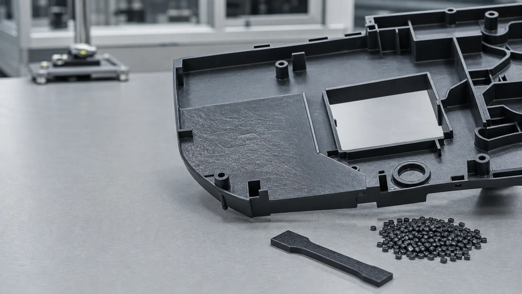
Glass fiber reinforced plastics are widely used in automotive, electronics, and industrial applications because unfilled resins often cannot provide the required rigidity, load bearing capability, or thermal stability. One persistent challenge is glass fiber exposure, also called floating fiber or fiber read-through. Parts can leave the mold with pale streaks and a roughened surface even after apparently reasonable molding adjustments.
Table of Contents
What Is Glass Fiber Exposure?
Glass fiber exposure refers to visible reinforcing fibers at the surface of an injection molded part. In cosmetic components this may appear as white streaking, uneven gloss, or a rough texture that follows the flow direction. It is not simply a color issue: it signals that the resin-rich surface layer did not fully cover the reinforcement.
Once fibers become visible at the surface:
- Surface roughness and visual inconsistency increase.
- Gloss variation and weld-line appearance become more difficult to control.
- Painting, coating, and decorative finishing become less reliable.
- Visible automotive interior and appliance housing parts may fail inspection.
- Local performance can be compromised when severe fiber-rich zones or weak weld lines are present.
The Root Cause: Fiber and Resin Flow Differently
Floating fiber is best understood as a two-phase flow and surface-freezing problem. Glass fibers and molten polymer do not respond identically to shear, orientation, wall contact, and cooling. Glass fiber density is typically about 2.5-2.6 g/cm3, while common thermoplastic matrices are commonly around 0.9-1.2 g/cm3. In high-speed injection molding, however, surface exposure is driven primarily by fountain flow, fiber orientation, wetting, and rapid skin solidification rather than gravity alone.
During filling, the advancing melt front rolls outward toward the cavity wall. Reinforcing fibers are transported and oriented by this flow. When the resin contacting the colder steel surface freezes before near-wall fibers are completely encapsulated, fiber ends or fiber-rich streaks remain visible after ejection.
Why the Same Reinforced Material Performs Differently Between Factories
Two molders can process the same compound and obtain very different surface quality. Part thickness, gate position, runner pressure loss, mold surface finish, venting, cooling layout, screw shear history, and injection profile all change where fibers orient and when the surface freezes. In practical terms, the stable process is the one that keeps reinforcement below an adequately resin-covered skin layer before solidification.
1. Mold Temperature
Mold temperature is one of the first parameters to investigate in a floating fiber defect. A cavity surface that is too cold causes an early frozen skin. Fibers arriving near the wall are locked into the surface before the polymer matrix has enough time to cover them.
When the mold is too cold
- Skin layer freezes too quickly.
- Surface wetting and encapsulation are reduced.
- Fiber streaks and dull patches become more visible.
With an optimized mold temperature
- Skin formation is delayed appropriately.
- Resin has more time to cover near-surface fibers.
- Gloss and appearance consistency can improve.
The correct setting must remain within the processing window of the base resin and part design. Increasing mold temperature without checking shrinkage, warpage, sticking, and cycle time can trade one defect for another.
2. Injection Speed Profile
Faster filling is not automatically a surface-quality solution. Excessive speed can produce high shear, strong fiber orientation at the wall, jetting, or turbulence near changes in geometry. Excessively slow filling can also be harmful because the resin freezes early and leaves fibers exposed before packing is effective.
A practical multi-stage approach
Use medium-low speed through the gate and sensitive entry region to reduce jetting and abrupt fiber disturbance.
Use controlled medium-high speed through most of filling, commonly up to about 90% of cavity volume, to avoid premature freezing.
Reduce speed near the end of fill to limit surface turbulence, burning, and fiber accumulation at flow-end areas.
3. Glass Fiber Length
Long fiber architectures generally make high cosmetic surface quality more difficult than short fiber systems. Longer fibers experience stronger orientation effects, bridge across flow features more readily, and have greater potential to protrude through a thin resin-rich surface layer.
For appearance-sensitive molded components, short glass fiber compounds are often easier to manage. A practical final fiber-length target may be approximately 0.2-0.4 mm, depending on the required mechanical performance and part surface specification.
Processing must also avoid unnecessary fiber breakage. Excessive screw shear may improve apparent surface behavior by shortening fibers, but it can also erode stiffness, strength, and creep performance. Surface quality and structural performance must be optimized together.
When Process Optimization Is Not Enough
If mold temperature, injection speed profile, venting, gate position, and fiber length have already been evaluated but visible read-through remains unacceptable, the next improvement often comes from the compound formulation.
Low Floating Fiber Formulation Technology
Modern low-floating-fiber reinforced compounds can use:
- Interfacial compatibilizers to improve bonding between polymer matrix and glass reinforcement.
- Lubricants and processing modifiers to support stable filling and reduce adverse surface drag.
- Wetting modifiers that improve resin coverage of the reinforcement.
These adjustments can improve resin-fiber wetting, increase fiber encapsulation, and reduce surface migration. In suitable systems, a specialized additive package at around 3% can reduce visible floating fiber defects by more than 50%, although performance must be confirmed for the selected resin, color, flame-retardant package, mold, and acceptance standard.
How to Verify the Defect Is Controlled
A single good-looking sample is not enough. The corrected process or compound must be verified across repeat production and under the intended appearance requirement.
| Check | Purpose |
|---|---|
| Visual inspection under consistent light | Compare fiber streak visibility, gloss uniformity, and weld-line appearance. |
| Process-window trial | Confirm the result remains stable across realistic mold temperature and fill-speed variation. |
| Mechanical retention test | Ensure fiber-length or formulation changes do not sacrifice required stiffness and impact behavior. |
| Customer surface standard review | Approve appearance against visible-part criteria before mass production release. |
Recommended Material Solutions
YicaiPlas develops reinforced and modified plastic compounds for appearance-sensitive and structure-critical injection molded parts. Relevant solution directions include:
- Low-floating-fiber reinforced compounds: improved fiber wetting and surface quality for visible molded components.
- Glass fiber reinforced engineering plastics: controlled rigidity and dimensional stability for structural applications.
- Custom modified plastics: balance surface appearance, mechanical performance, processing stability, color, UV resistance, or flame retardant requirements.
Engineering FAQ
What causes glass fiber exposure in injection molded parts?
Glass fiber exposure occurs when fibers are transported toward the cavity surface during fountain flow and the resin skin freezes before the fibers are fully encapsulated. Mold temperature, flow speed, fiber length, part geometry, and compound wetting behavior all influence the defect.
Does higher mold temperature reduce floating fiber?
A properly increased mold temperature can delay skin freezing and give the resin more time to wet and cover near-surface fibers. The usable temperature range still depends on the base resin, cycle-time target, dimensional tolerance, and release behavior.
Is faster injection always better for glass fiber surface quality?
No. Excessive speed may increase shear-driven orientation and visible fiber streaks, while excessively slow filling may freeze the surface too early. Multi-stage filling is commonly used to balance flow stability and surface encapsulation.
When should a low-floating-fiber compound be considered?
A low-floating-fiber formulation should be evaluated when surface requirements remain unmet after mold temperature, speed profile, gate design, venting, and fiber length have been optimized, especially for visible automotive or appliance components.
Need Help Reducing Glass Fiber Exposure in Molded Parts?
YicaiPlas provides customized reinforced plastic material solutions for automotive, electronics, and industrial injection molding applications, including surface-sensitive components that require controlled floating fiber performance.
Contact Our Engineering TeamRelated Technical Articles
Glass Fiber Reinforced Nylon Warpage
Understand fiber orientation, anisotropic shrinkage, cooling imbalance, and dimensional stability in PA6 GF and PA66 GF parts.
Injection Molding Flash Troubleshooting
How pressure, clamp force, mold wear, and material viscosity cause recurring flash defects.
Part Sticking and Mold Release Problems
Practical troubleshooting for demolding force, draft angle, mold surface condition, and release-modified compounds.
PC+ABS Injection Molding Shrinkage
Why sink marks and shrinkage persist when gate freeze and cooling imbalance prevent proper shrinkage compensation.
Related Material Solutions
Modified Plastics and Custom Compounding
Reinforced, low-floating-fiber, UV resistant, flame retardant, and impact modified compounds.
High Impact Plastic Solutions
Engineering plastics for structural, automotive, power tool, and industrial applications.
Automotive Plastic Applications
Material solutions for interior, exterior, reinforced, and functional automotive plastic parts.