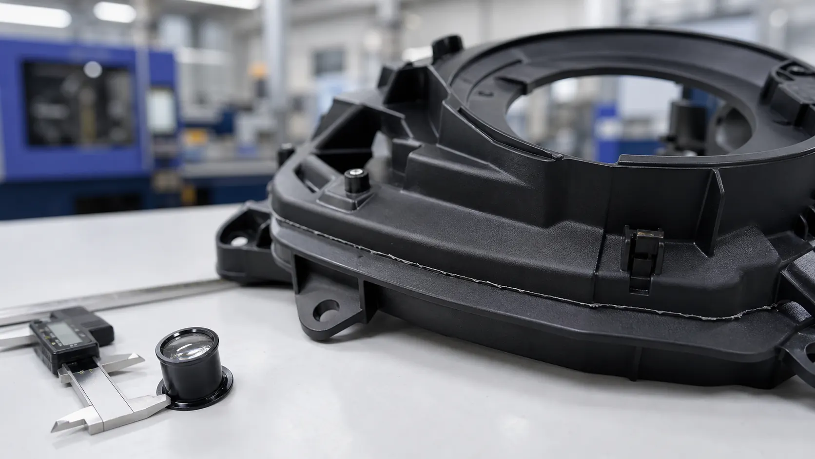
A production batch was returned by a customer because the parting line had flash of only about 0.1 mm. The dimension looked small on paper, but it was enough to interfere with assembly, create hand-feel issues, and trigger a complete quality complaint. The factory tried hand trimming. Operators could only process limited quantities per day, trimming marks became visible, and the same defect appeared again in the next run.
This is why injection molding flash should not be treated as a simple appearance problem. In PC/ABS molding, flame retardant compounds, glass fiber reinforced materials, and large automotive plastic parts, recurring flash is often a warning signal that the whole molding system is no longer stable.
Table of Contents
What Is Injection Molding Flash?
Injection molding flash is excess molten plastic that escapes from the intended cavity boundary during filling or packing. It usually appears along the mold parting line, slider shutoff areas, ejector pin clearances, insert edges, core shutoffs, or weak sealing surfaces.
In small consumer parts, flash may first look like a cosmetic defect. In industrial production, the impact can be far more serious:
- Assembly interference and unstable snap-fit performance.
- Manual trimming cost and inconsistent secondary finishing quality.
- Blocked automation, robot handling, or fixture positioning.
- Customer complaints caused by sharp edges, burrs, and visible parting-line defects.
- Hidden mold wear that becomes worse with every production cycle.
Why Increasing Clamping Force Often Makes Things Worse
Many technicians respond to flash by increasing clamping force. Sometimes this provides temporary improvement. But if the root cause is venting imbalance, mold wear, excessive packing, or material flow variation, higher clamp force can create new problems.
Excessive clamping can compress the parting surface so tightly that gas cannot escape. The result may be burn marks, gas traps, silver streaks, poor weld-line quality, or higher residual stress. In other words, one defect is suppressed while another defect is created.
What Actually Causes Flash?
1. Mold Gap Instability
Flash begins when molten resin finds a leakage path. In sensitive molds, a clearance on the order of hundredths of a millimeter can be enough for resin to escape, especially under high cavity pressure. Parting surface wear, poor spotting, slider mismatch, insert movement, and ejector clearance all create potential leakage paths.
2. Insufficient Clamping Force Margin
Clamping force must resist cavity pressure across the projected area of the part and runner system. If the required clamp force is close to the machine limit, small changes in melt viscosity, temperature, transfer position, or packing pressure can open the mold slightly and produce flash.
This risk increases with thin-wall parts, high-flow resins, large automotive housings, and materials such as modified plasticsthat may be supplied in different reinforced, flame retardant, or impact-modified grades.
3. A Process Window That Is Too Narrow
Melt temperature, injection speed, V/P transfer position, and packing pressure all influence cavity pressure. A small temperature increase can reduce viscosity enough to make the same mold begin flashing. Excessive packing pressure may also force resin into clearances that were stable during filling.
The same logic appears in shrinkage troubleshooting: pressure alone cannot solve every defect. For a related discussion, see our engineering guide on PC+ABS injection molding shrinkage and packing pressure.
4. Insufficient Mold Rigidity
Some molds are not rigid enough under real injection pressure. Large plates, weak support pillars, insufficient backing, or uneven load distribution can allow elastic deformation during filling. Even if the mold looks well fitted when static, it may open under dynamic cavity pressure.
5. Material MFI Variation
Recurring flash is sometimes caused by material variation. PC/ABS, flame retardant ABS, reinforced PA, and regrind-containing formulations can show noticeable flow changes from moisture, filler dispersion, additive systems, or batch-to-batch MFI variation. If the mold and process are already operating near the edge, a small material flow change can push the part into flash.
How to Systematically Reduce Flash
Recalculate Clamping Force Safety Margin
Recheck projected area, estimated cavity pressure, machine clamp force, and safety margin. A practical production target is to keep enough reserve margin so normal material and process variation does not open the mold. Mold flow simulation and cavity pressure measurement are valuable when the part is large, thin-walled, or safety critical.
Inspect Parting Surface Condition
Use spotting compound, pressure paper, or precision inspection to check real contact condition. For demanding parts, contact area and shutoff pressure should be evaluated at the actual sealing surfaces, not only by visual inspection after mold assembly.
Balance Mold Venting
Poor venting can force the process into an unstable compromise: enough pressure to fill the part creates flash, while lower pressure creates short shots or burn marks. Vent depth and vent location must be designed for the specific resin, whether the material is ABS, PC/ABS, PP, PA6 GF30, or a flame retardant compound.
Use Multi-Stage Injection Control
Instead of using one aggressive injection speed, many molds benefit from a staged profile: controlled gate entry, stable main filling, then reduced speed near the end of fill before packing. This lowers peak pressure spikes and improves repeatability around the parting line.
Control Material Variation
If flash appears only after a material lot change, review MFI, moisture level, filler content, recycled content, and drying conditions. This is particularly important for reinforced grades where surface quality and flow stability are also affected by fiber behavior. Our article on glass fiber exposure in injection molding explains how reinforced materials can behave differently from unfilled resins.
How to Confirm Flash Is Under Control
Flash is not truly solved just because one trial shot looks acceptable. Verification should include repeat production, cavity-to-cavity comparison, material lot confirmation, and downstream assembly checks.
- Run enough consecutive shots to confirm that the process window is stable.
- Inspect all cavities, sliders, inserts, ejector areas, and parting-line transitions.
- Confirm that trimming is no longer required for functional or cosmetic acceptance.
- Check assembly fixtures, snap-fit areas, and automated handling points.
- Repeat key checks after material lot change, color change, or drying-condition change.
Recommended Material Solutions
When mold and process changes are limited, material selection can help widen the molding window. YicaiPlas supports engineering plastic applications with flow-balanced, reinforced, impact-modified, and flame retardant formulations.
Stable Flow PC+ABS
Balanced viscosity for large housings and automotive trim parts.
Glass Fiber Reinforced Compounds
Stiffness and dimensional support for structural molded parts.
High Impact Engineering Plastics
Improved toughness for snap-fit and assembly-sensitive components.
For parts requiring impact durability, review our high impact plastics solutions and application support for automotive, electronics, and industrial molding programs.
Engineering FAQ
What is injection molding flash?
Injection molding flash is excess plastic that escapes from the mold cavity through the parting line, slider gaps, ejector clearances, insert areas, or other sealing interfaces during filling or packing.
Why does flash come back after trimming or process adjustment?
Recurring flash usually means the mold sealing system is unstable. Mold wear, clamp force margin, cavity pressure, venting balance, mold rigidity, and material flow variation must be checked together.
Does increasing clamping force always solve injection molding flash?
No. Higher clamping force may temporarily reduce mold opening, but it can also close vents and create gas traps, burn marks, silver streaks, or stress problems if the root cause is not addressed.
Why are PC/ABS and glass fiber reinforced materials sensitive to flash?
PC/ABS, flame retardant compounds, and glass fiber reinforced plastics can show large changes in flow behavior with melt temperature, moisture, additives, filler content, and batch variation. A narrow process window can make flash unstable.
How should injection molding flash be solved systematically?
Start with clamp force and mold sealing checks, then inspect parting surface contact, venting, mold plate rigidity, injection speed profile, V/P transfer position, packing pressure, and material MFI consistency.
Related Technical Articles
Part Sticking in Mold: Causes and Solutions
A practical guide to demolding force, draft angle, mold surface condition, packing pressure, and material-related sticking.
PC+ABS Injection Molding Shrinkage
Understand why packing pressure alone cannot solve sink marks when gate freeze and cooling imbalance limit shrinkage compensation.
Glass Fiber Reinforced Nylon Warpage
Engineering analysis of fiber orientation, anisotropic shrinkage, mold temperature balance, and dimensional control.
Glass Fiber Exposure and Floating Fiber
How process conditions, fiber wetting, and compound formulation affect surface appearance in reinforced plastics.
Related Material Solutions
Modified Plastics
Custom PC/ABS, reinforced plastics, and functional compounds for stable injection molding.
High Impact Plastic Solutions
Material options for parts requiring toughness, stiffness, and repeated impact resistance.
Automotive Plastic Applications
Material support for interior, exterior, structural, and electronic automotive components.
Looking for Stable PC/ABS or Reinforced Engineering Plastics?
YicaiPlas provides customized PC/ABS compounds, glass fiber reinforced engineering plastics, color matching, and molding optimization support for automotive, electronics, and industrial applications.
Contact Our Engineering Team